
 A protective device coordination study is the evaluation of the system’s overcurrent protective devices, such as relays, fuses and circuit breakers and the circuits they protect. The coordination study compares each device’s operating current levels and the length of time within which each protective device operates, in order to properly operate without system damage or failure.
Coordination studies are performed to ensure that the protective device closest to the overload or short circuit condition is the one that operates in order to isolate the failure as quickly as possible.
Key Objectives of Electrical Coordination Studies
- Minimize Downtime
- Ensure that if there’s a short circuit or overload, only the affected portion of the system shuts down.
- Prevent unnecessary outages of larger sections of the facility.
- Protect Equipment
- Prevent damage to transformers, generators, cables, and other electrical components by setting protective devices correctly.
- Enhance Safety
- Reduce the risk of arc flash incidents and protect personnel by properly controlling fault energy levels.
- Compliance with Codes & Standards
- Required by NEC (National Electrical Code) for certain facilities such as hospitals, data centers, and emergency systems.
- Typically done per NFPA 70, NFPA 70E, and IEEE standards.
Key Components of the Study
The process involves reviewing the entire electrical distribution system, from the utility feed to the final circuits, and setting devices so they operate in the correct sequence.
- Data Collection
- Utility service data (available fault current, voltage)
- One-line diagrams of the electrical system
- Specifications of protective devices:
- Circuit breakers
- Fuses
- Relays
- Motor protection
- Cable sizes and lengths
- Short Circuit Study
Before coordination can be done, engineers run a short circuit analysis to:
- Determine maximum and minimum available fault currents.
- Verify that protective devices can withstand and interrupt those fault levels.
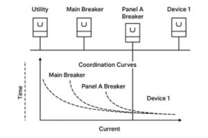
- Time-Current Curves (TCC)
Engineers plot time-current curves for each device.
- Time-current curve: A graph showing how quickly a device will trip at different current levels.
- Goal: Stagger the curves so that smaller, downstream devices operate before upstream devices.
Example:
- A branch circuit breaker should trip before a main panel breaker for a fault in one branch circuit.
- Device Settings & Adjustments
- Adjust trip settings on circuit breakers and relays.
- Choose fuse types with proper ampere ratings and characteristics.
- Ensure there’s adequate separation between operating curves to prevent overlap and nuisance tripping.
- Reporting & Documentation
Where Coordination Studies Are Critical
Some industries require selective coordination by code:
- Hospitals & Healthcare Facilities – to ensure life safety equipment stays powered.
- Data Centers – to maintain uptime and avoid cascading outages.
- Industrial Plants – to protect expensive machinery and minimize production loss.
- High-rise Buildings – for emergency systems like elevators and fire pumps.
Benefits of Performing a Coordination Study
- Fewer unnecessary outages
- Improved system reliability
- Reduced risk of arc flash hazards
- Compliance with NEC and NFPA 70E
- Prolonged equipment life
- Peace of mind during inspections and audits
Is your company in need of coordination studies?